OeS 6 software is intended for modeling and calculation of radial and multiply closed power networks, under operating and short-circuit conditions. The program’s computational capabilities allow for the analysis of the operation of HV, MV and LV networks within one model. The program is also equipped with modules supporting the selection of protection settings and determining the load capacity of cables depending on the installation conditions. OeS has always been created as an engineering tool – it is characterized by transparency and simplicity of use, while maintaining a full range of computational functionalities for the implementation of analytical and design tasks.

Individual OeS software modules allow you to perform power flow and short-circuit calculations, which are an indispensable element of every project or connection expertise. Available functionalities enable, among others: proper selection of devices with regard to operation in operating and short-circuit conditions, solving problems related to reactive power compensation or assessment of the operation of the neutral point. They also support planning the expansion of the existing network and help in making connection decisions. In the OeS software, you can quickly perform calculations for any network configuration, which opens up great opportunities for users to create multi-variant analyses.

Functionalities related to modeling and analysis of network security operation have also been developed for many years. The user can analyze the sensitivity and selectivity of protections, determine their response times, and assess the risk of shock. Additionally, OeS can be equipped with the PROKAB module, which allows for the creation and calculation of the longitudinal and transverse profiles of the cable and the determination of substitute parameters for overhead lines. Another additional element is the GRAFIK module, which allows for the modeling of consumers taking into account the variability of the load over time (operator’s tariff or measurement data) and the modeling of prosumers taking into account the variability of their generation. The possibility of using the ENTSO-E database (climate years) has been implemented here, taking into account the weather forecast in the calculations or entering measurement data. Computational functionalities allow for the analysis of time histories of power and branch currents, voltages in network nodes, losses and other network parameters.

Power flow

The module is used to perform calculations in network operating conditions. The calculations result in currents in the branches and voltages in the network nodes. Additionally, the program calculates transverse and longitudinal active and reactive losses in network elements and total losses, as well as the power factor and the required reactive power compensation power to the given power factor at the network point. After entering the values of the limit parameters of network elements, it is possible to analyze the degree of load on branch elements and identify exceedances of these parameters.

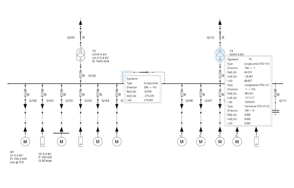
Flow calculations are performed using the nodal potential method in a non-topological approach. The default number of calculation iterations is 1, in this case the branch current is determined based on the nominal node voltages. When selecting a larger number of subsequent iterations, the voltages are modified by voltage drops, increasing the precision of the calculations. An additional functionality of the module for determining the flow of operating currents is the visual arrowing of power lines in relation to the active or reactive value of branch currents. If the arrow function is activated, after calculating the flow of operating currents on the power lines forming the diagram of the analyzed network, arrows will appear showing the direction of flow of the selected current component.

Full results of calculations of the flow of operating currents are available in the result window below.

All calculated parameters have been grouped in the result window and are visible in Tabs, as shown below:

Node Results Tab:

  • active part of the real voltage in the Re{U} node (kV),
  • reactive part of the real voltage at the node Im{U} (kV),
  • real voltage module at the U node (kV),
  • voltage deviation U d (%) – relative difference in the actual voltage in the node related to its level
  • voltage (nominal voltage),
  • voltage drop U dr (kV) – voltage difference of the reference node and the actual voltage in a given node,
  • percentage voltage drop U dr (%) – relative voltage difference of the reference node and the actual voltage in a given node,
  • actual voltage level U p (kV) – nodal voltage resulting from the actual transformer ratio,
  • reference node index – number of the node relative to which the voltage drop is determined,
    name of the reference node.

Branch results tab:

  • branch voltage U (kV) – branch voltage level,
  • active part of the branch current Re {I} (A),
  • reactive part of the branch current Im {I} (A),
  • branch current module I (A),
  • active power P (kA) – power determined from the active part of the current and the branch voltage value,
  • reactive power Q (kvar) – power determined from the reactive part of the current and the branch voltage value,
  • apparent power S (kVA) – power determined from the branch current and voltage,
  • longitudinal active power losses ∆P along (kW),
  • lateral active power losses ∆P pop (kW),
  • longitudinal reactive power losses ∆Q along (kvar),
  • lateral reactive power losses ∆Q pop (kvar),
  • standard long-term current capacity I dd (A) – current load capacity of the element depending on its type:
    • for power lines – the standard long-term current capacity given for the element or, in the absence thereof – the calculated long-term current capacity,
    • for series compensators and filters – the rated current value given in the element dialog box,
    • for the switch – the standard long-term current capacity given for the element,
    • for transformers – the maximum operating current of a given winding or the rated current of a given winding given for the element,
  • calculated long-term current capacity I d (%) – relative level of load,
  • exceeds – signaling of exceedance of the long-term current capacity,
  • power angle ϕ (°) – angle of the branch load vector,
  • cosϕ – branch load power factor,
  • type of load – type of reactive power load, depending on its sign: inductive or capacitive,
  • compensation power (kvar) – virtual capacitive power that should be added to the node so that the branch load power factor is equal to the required value defined in the scheme configuration,
  • voltage drop U dr (kV) – absolute value of the algebraic difference of nodal voltage modules; value determined only for power lines, series compensators and filters,
  • percentage voltage drop U dr (%) – voltage drop related to the branch voltage,
  • summary load factor kz – product of demand factors of all branch elements, taking into account globally defined values.

Summary power losses tab – total losses of individual power components divided into types of network elements,

Limit exceeds tab – list of elements for which exceedances were detected, these results can also be found in the Branch Results tab.