OeS 6 software is intended for modeling and calculation of radial and multiply closed power networks, under operating and short-circuit conditions. The program’s computational capabilities allow for the analysis of the operation of HV, MV and LV networks within one model. The program is also equipped with modules supporting the selection of protection settings and determining the load capacity of cables depending on the installation conditions. OeS has always been created as an engineering tool – it is characterized by transparency and simplicity of use, while maintaining a full range of computational functionalities for the implementation of analytical and design tasks.

Individual OeS software modules allow you to perform power flow and short-circuit calculations, which are an indispensable element of every project or connection expertise. Available functionalities enable, among others: proper selection of devices with regard to operation in operating and short-circuit conditions, solving problems related to reactive power compensation or assessment of the operation of the neutral point. They also support planning the expansion of the existing network and help in making connection decisions. In the OeS software, you can quickly perform calculations for any network configuration, which opens up great opportunities for users to create multi-variant analyses.

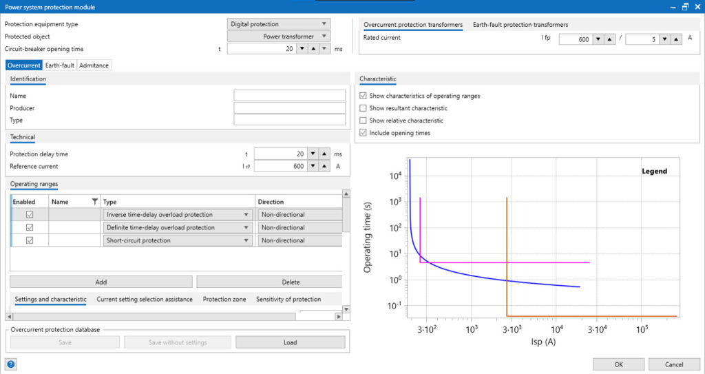
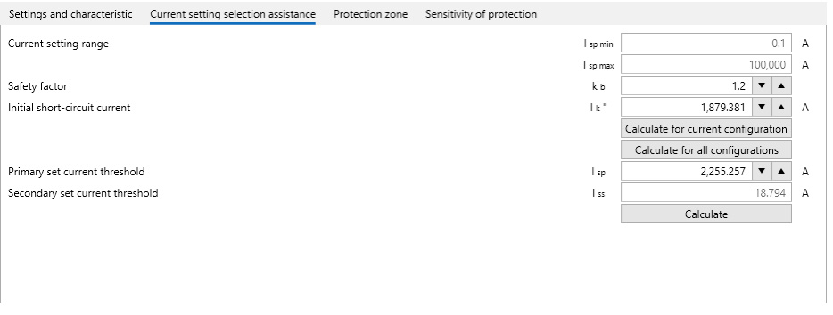
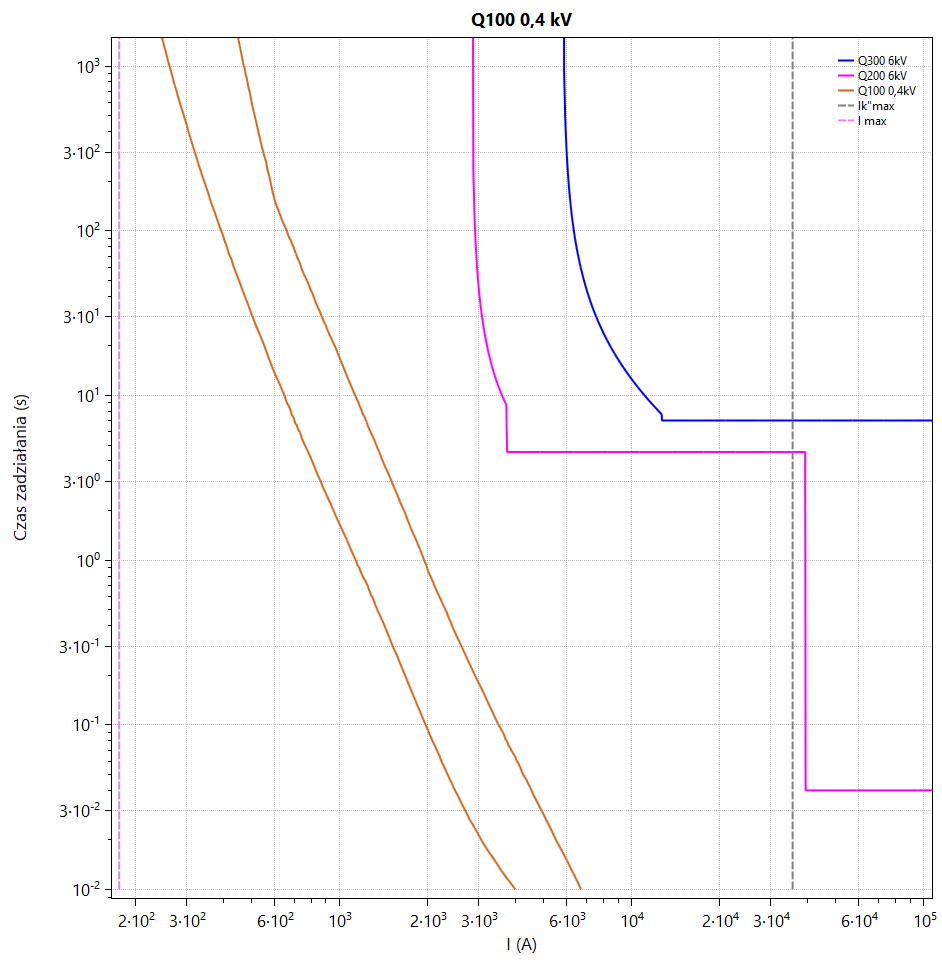
Functionalities related to modeling and analysis of network security operation have also been developed for many years. The user can analyze the sensitivity and selectivity of protections, determine their response times, and assess the risk of shock. Additionally, OeS can be equipped with the PROKAB module, which allows for the creation and calculation of the longitudinal and transverse profiles of the cable and the determination of substitute parameters for overhead lines. Another additional element is the GRAFIK module, which allows for the modeling of consumers taking into account the variability of the load over time (operator’s tariff or measurement data) and the modeling of prosumers taking into account the variability of their generation. The possibility of using the ENTSO-E database (climate years) has been implemented here, taking into account the weather forecast in the calculations or entering measurement data. Computational functionalities allow for the analysis of time histories of power and branch currents, voltages in network nodes, losses and other network parameters.

Protections

The module is used to analyze the protection systems, in particular to support the selection of protection settings and the analysis of their sensitivity and selectivity. It is possible to implement overcurrent, earth-fault and admittance protection characteristics. Combined with the results of short-circuit calculations, the module allows you to quickly read the activation time of the protection of the analyzed point and determine the speed of its shutdown.

The protection selection module in the OeS 6 program supports the User in the following areas:

  • modeling of overcurrent, earth-fault and admittance protection
  • selection of settings,
  • determining the sensitivity factors of protection elements,
  • checking the selectivity of protection devices,
  • checking the protection response time,
  • analysis on the admittance plane.

Protection modeling
The protection is directly assigned to the switch, which is the executive object.

The parameterization of the protection begins with the selection of its type, and in the OeS program, the protections are divided into three main groups:

  • fuses and fuse switches with band fuse characteristics,
  • installation circuit breakers with time-dependent band characteristics with an independent short-circuit element,
  • digital security defined by any dependency (function).

For each type of protection and level of digital protection, the protection zone and the expected sensitivity factor must be determined. For this purpose, use the appropriate tabs in the protection parameters panel.

Fuse protection parameterization

Parameterizing the fuse involves completing the tables defining the edges of the protection response area. Data tables can be filled in in one of the following ways:

  • retrieving data from the protection database
  • by downloading points from an external CSV file
  • pasting the coordinates of the points from the spreadsheet

Parameterization of the circuit breaker

The first stage of parameterization is to enter the breaker’s own time and rated current. The first range of the circuit breaker characteristic consists of a band defined by points. The second setting is the activation limit of the instantaneous short-circuit element, which reacts in a band depending on the defined trigger current multiples. You can also download protection parameters stored in the protection database.

Parameterization of digital protection

Using the digital protection class, any characteristics of overcurrent, earth fault and admittance protection can be modeled. Parameterization should start with the selection of a security criterion.

The total response time of the protection unit is the sum of the following times:

  • the connector’s own time,
  • own security time
  • delay settings of the energized element.

The protection parameters for the independent element are entered using the following data
current setting range:

  • minimum Ispmin (A) and maximum Isp max (A) setting
  • Isp(A) current setting
  • current setting on the secondary side Iss(A) – determined automatically after entering the current transformer parameters,
  • relative current setting Isp/IrP – setting related to the protection reference current,
  • time setting range: minimum tmin (s) and maximum tmax (s) setting
  • operation delay of the protection stage t (s).

The protection parameters for the dependent element are defined using the following data:

  • current setting range: minimum setting Ispmin (A) and maximum setting Isp max (A),
  • Isp(A) current setting – which is also the vertical asymptote of the modeled characteristic,
  • current setting on the secondary side Iss(A) – determined automatically after entering the current transformer parameters,
  • relative current setting Isp/I rP – setting related to the protection reference current

The program allows you to enter characteristics in the form of:

  • points – similarly to modeling a fuse,
  • functions – using a database to which you can enter and download appropriate formulas (time-current characteristics).

The admittance protection parameters are entered using the following data:

  • select characteristics from the available list: admittance, conductance, susceptance, conductance-susceptance, conductance (forward), conductance (backward), susceptance (forward), susceptance (backward), admittance-conductance, admittance-conductance (forward), admittance-conductance (backward), admittance-susceptance, admittance-susceptance (forward), admittance-susceptance (backward),
  • depending on the characteristics: zero admittance, zero conductance, zero susceptance, correction angle,
  • start-up parameters: zero-sequence short-circuit current, zero-sequence voltage,
  • delay of activation of the protection stage.

Supporting the selection of digital protection settings
The setting selection support module allows for automatic determination of the current setting value depending on the type of protection and the protected object.
The criterion for selecting the setting depends on the type of protection:

  • For short-circuit protection, it is the short-circuit current flowing through the switch during a short-circuit at the end of the protected zone. This current can be entered directly or calculated using the “Calculate” button; selecting the “Calculate for all configurations” button allows you to determine the maximum short-circuit current for all saved network operating configurations.
  • For overload protection, it is the load current (determined during flow calculations for the current or all saved configurations of the network state) or the rated current of the protected element.

Protection database
The protection database allows you to save frequently used devices or individual protection elements. The fuse database contains band time-current characteristics of fuses saved as a set of points. Each characteristic family contains a number of characteristics for inserts with different rated currents. The circuit breaker database stores families of relative characteristics that are scaled by the rated current. The digital protection database stores data in two variants: a full representation of the parameterized protection (all stages, ranges, settings) or a new protection without settings (all stages and ranges, without specific settings).

Protection sensitivity calculations
Protection sensitivity calculations are used to determine sensitivity coefficients and to determine whether the determined coefficients are sufficient for the correct selection of protection measures.
The calculation results can be viewed in a diagram, after selecting the analyzed protection, or in a summary table of results. For all elements of the selected protection, the sensitivity factor is determined as the quotient of the two-phase short-circuit current at the end of the protected zone and the setting value.

Protection selectivity calculations
Selectivity analysis allows you to determine whether the protections in a given supply line are properly coordinated. For each protection selected for analysis, the program determines the power supply route and groups all protections on this route. Then, the resultant characteristics of the grouped protections are converted to the voltage level of the main protection and displayed together in one drawing.

The resultant selectivity analysis plot contains the following data:

  • information whether the protections in the analyzed sequence are selective – the minimum time interval between the protection characteristics is examined and is comparable to the set value in the calculation configuration,
  • designation of the power supply element,
  • name of the analyzed protection and its voltage level,
  • protection sequence diagram:
    • characteristics of all protections in the line converted to the voltage level of the analyzed protection,
    • minimum two-phase short-circuit current, determined for the short-circuit at the end of the analyzed protection zone,
    • maximum initial short-circuit current, determined for the place where the protection is installed,
    • module of the load current flowing through the analyzed protection for the current network operating condition.

Resultant characteristics of protection lines are also available from the results table.

Protection response time calculations
The analysis of protection response times allows determining the activation time of protections in response to the current flowing through them in various network operating states.

The result of the calculations is the response time of all protections to the current flowing through them during the indicated network state:

  • for short-circuit calculations:
    • overcurrent protection function – the response time is determined twice, for the maximum initial short-circuit current and for a three-phase short-circuit (the share of motors in the short-circuit current is omitted; voltage coefficient c = 1),
    • earth-fault protection function – response time is determined for the flow of single-phase short-circuit current, component 3I0,
  • for flow calculations – time is determined for the load current in working flows,
  • for motor starts – the time is determined for the maximum load current within the set analysis time of starting calculations.