The analysis of exceedances consists in checking the elements according to the given strength:
- surge – applies to busbars and connectors, exceeding the limit parameters is checked, i.e. peak current ipor surge current ip
- switching – applies to switches, the maximum breaking current Icuis checked for exceeding the symmetrical short-circuit breaking current of 20 ms calculated for a given element,
- thermal – applies to power lines, busbars and connectors, exceeding the thermal short-circuit current Ithr is checked.
Additionally, when analyzing exceedances for power lines, the temperature increase of the current path during a short circuit is also determined.
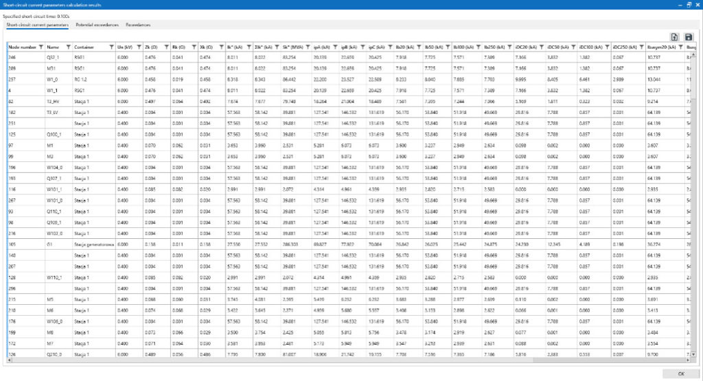
All calculated parameters have been grouped in the result window and are visible in tabs, as shown below:
- Fault current parameters tab:
- nominal voltage Un(kV) – nominal voltage (voltage level) of the network in which a given node is located,
- initial short-circuit current Ik” (kA) – modulus of the resultant complex value of the short-circuit current, calculated for all sources, Ik” = | ΣIk”i|
- total initial short-circuit current according to the share of sources ΣIk” (kA) – the sum of the modules of the complex values of individual short-circuit currents flowing to the short-circuit location from each source, ΣIk ” = Σ|Ik”i|,
- short-circuit power Sk” (MVA),
- peak short-circuit current ipA(kA) – the κ coefficient determined for the ratio R/X of the resultant impedance of the network affected by the short circuit is assumed, method in accordance with the standard,
- peak short-circuit current ipB(kA) – the value of the κ coefficient is assumed increased by 15% compared to that calculated in method A, the method recommended according to the standards for closed networks; in which high heterogeneity causes the R/X relations in individual branches of the replacement scheme to be different,
- peak short-circuit current ipC(kA) – is the sum of the components calculated for each short-circuit current source separately, based on a different coefficient κ – depending on the R/X ratio of a particular branch of the equivalent circuit; the most accurate method, but non-normative,
- short-circuit breaking current for 20 ms Ib20(kA) – symmetrical,
- short-circuit breaking current for 50 ms Ib50(kA) – symmetrical,
- short-circuit breaking current for 100 ms Ib100(kA) – symmetrical,
- short-circuit breaking current for 250 ms Ib250(kA) – symmetrical,
- aperiodic component of the short-circuit current for a time of 20 ms iDC20(kA) – aperiodic component current,
- aperiodic component of the short-circuit current for a time of 50 ms iDC50(kA) ) – aperiodic component current,
- aperiodic component of the short-circuit current for 100 ms iDC100(kA) ) – aperiodic component current,
- aperiodic component of the short-circuit current for a time of 250 ms iDC250(kA) ) – aperiodic component current,
- asymmetrical short-circuit breaking current for 20 ms Ibasym20(kA) – Ib supplemented by iDC,
- asymmetrical short-circuit breaking current for 50 ms Ibasym50(kA) – Ib supplemented by iDC,
- asymmetrical short-circuit breaking current for 100 ms Ibasym100(kA) – Ib supplemented by iDC,
- asymmetrical short-circuit breaking current for 250 ms Ibasym250(kA) – Ib supplemented by iDC,
- steady-state short-circuit current Ik(kA),
- thermal equivalent of short-circuit current of specified time – value determined on the basis of the coefficients m and n Ith (t s)(kA),
- thermal equivalent of short-circuit current of specified time converted to 1 s Ithr(1s)(kA),
- thermal equivalent of short-circuit current of specified time converted to 3 s Ithr(3s)(kA),
- Potential exceedances tab:
-
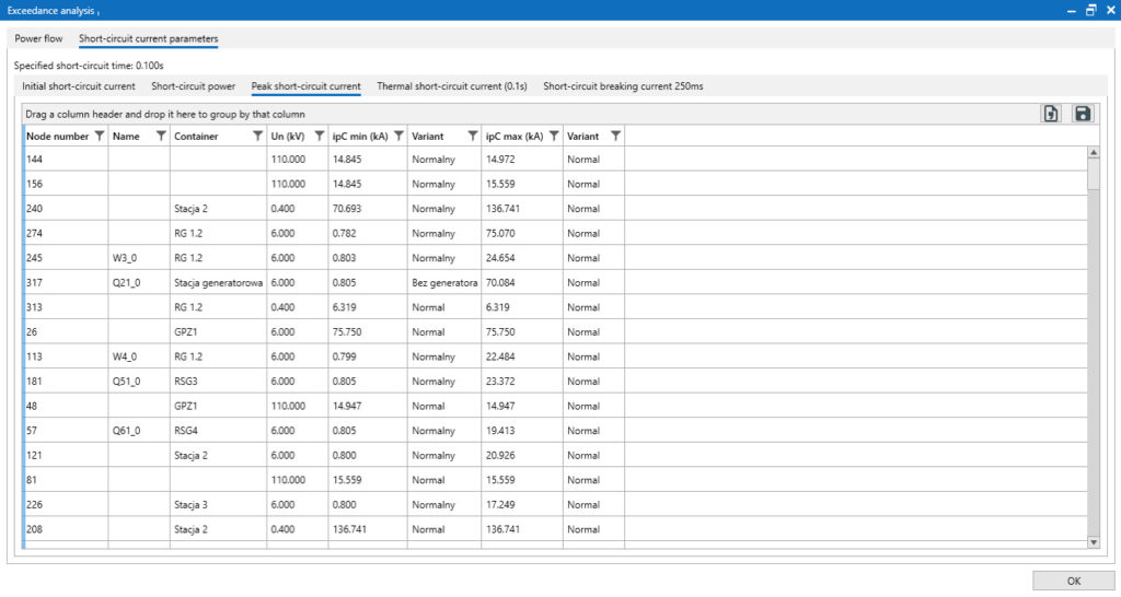
- busbar surge current or switch peak current ipr(kA) – basis for determining the exceedance of the surge strength,
- impact load degree ip/i pr(%),
- exceeding (impact strength) – signals exceedance when (ip/ipr)> > 100%,
- maximum breaking current of the switch Icu(kA) – basis for determining the switching strength,
- connector load degree Ib/Icu(%),
- exceeding (connective strength) – signals exceedance when (Ib/Icu)> > 100%,
- thermal short-circuit current 1 s Ithr(kA) for the switch and busbar, and for the power line, for which this parameter is determined on the basis of the permissible one-second short-circuit current density Ithr (kA),
- degree of heat load Ithr(t)/Ithr(%),
- exceedance (thermal strength) – indicates an exceedance when (Ithr(t)/Ithr)> > 100%,
- temperature rise during a short circuit ΔT (K) – only for power lines.
- Exceedances tab – based on short-circuit current flow calculations
Calculation of minimum parameters of symmetrical short-circuit current.
Determination of the minimum parameters of symmetrical short-circuit current is performed analogously to the calculation of the parameters of symmetrical short-circuit current. The important differences are:
- adopt the minimum values of the voltage coefficient “c” – respectively, for the nominal voltage of the network,
- ignoring the effect of impedance correction factors of transformers and synchronous generators,
- ignoring the impact of prosumer sources (wind farms, photovoltaics and others), synchronous and asynchronous motors on the value of short-circuit current,
- taking into account the increase in resistance of the current paths resulting from the heating of the wires
All calculated parameters, presented in the resulting window, are shown below:
- nominal voltage Un(kV) – nominal voltage (voltage level) of the network in which the node is located,
- the minimum initial short-circuit current Ik “3fmin(kA) – the modulus of the resultant value of the combined short-circuit current, calculated for all sources, Ik” = |ΣIk” i|,
- summary min. initial short-circuit current according to the shares of the sources ΣIk” min(kA) – the sum of the modules of the combined values of the individual short-circuit currents, flowing to the site of the short circuit from each source, ΣIk” = Σ|Ik “i|,
- Minimum two-phase initial short-circuit current Ik “2fmin(kA),
- minimum short-circuit power Sk “min(MVA),
- minimum steady-state short-circuit current Ikmin(kA),
- minimum two-phase initial fault current Ik “2f min G(kA) – calculated according to mining standard PN-G-42042 Ik “2f min G (kA).
Calculation of symmetrical short-circuit current flow
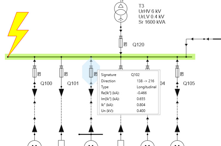
The calculation of the symmetrical short-circuit current flow allows the analysis of the branch components of the short-circuit current and nodal voltages, assuming a short circuit at the selected node of the network.
All calculated parameters have been grouped in the resulting window and can be seen in tabs, as shown below:
- Node Results tab:
- nominal network voltage Un(kV),
- the real part of the voltage at a given node of the network during a short circuit Re{U} (kV),
- the imaginary part of the voltage at a given node of the network at the time of the short circuit Im{U} (kV),
- Voltage modulus at a given network node during a short-circuit U (kV),
- Branch Results tab:
- nominal branch voltage Un(kV),
- the real part of the short-circuit current, flowing in a given branch of the network during the short circuit Re{Ik“} (kA),
- imaginary part of the short-circuit current, flowing in a given branch of the network during the duration of a short circuit Im{Ik“} (kA),
- the modulus of the short-circuit current, flowing in a given branch during a short circuit Ik” (kA).
Calculation of parameters of asymmetrical short-circuit current
In the calculation of asymmetrical short-circuit current, a transformer is modeled depending on the connection arrangement of its windings. The modeled connection arrangements include:
- for double-winding transformers:
- grounded star – delta, YnD,
- grounded star – star, YnY,
- star grounded – star grounded, YnYn,
- star – star, YY,
- star – delta, YD,
- zigzag grounded – star grounded, ZnYn,
- autotransformer: star grounded – delta, YnD.
- for three-winding transformers:
- star grounded – star grounded – delta, YnYnD,
- star grounded – star – delta, YnYD,
- grounded-star – delta – delta, YnDD.
The connection arrangements, not described above, provide a break for the zero component in asymmetrical calculations. In the calculation of asymmetrical fault current, synchronous and asynchronous motors are not considered as sources of fault current.
The calculation of the parameters of unsymmetrical short-circuit current includes many variants of the analyzed disturbance, they include:
- single-phase short circuit,
- single-phase short circuit with neutral conductor (only for low-voltage network),
- two-phase short circuit,
- two-phase short circuit with earth,
- three-phase short circuit
All calculated parameters have been grouped in the resulting window and can be seen in tabs – according to the type of interference analyzed. These parameters include:
- nominal voltage Un(kV) – the nominal voltage of the network in which the node is located,
- short-circuit current of the zero component I0(kA),
- short-circuit current of the compliant component I1(kA),
- short-circuit current of the opposite component I2(kA),
- L1 phase short-circuit current IL1(kA),
- L2 phase short-circuit current IL2(kA),
- L3 phase short-circuit current IL3(kA),
- real part of the short-circuit loop impedance Re{Z} (Ω),
- imaginary part of the short-circuit loop impedance Im{Z} (Ω),
- modulus of short-circuit loop impedance Z (Ω).
Parameters for a single-phase short circuit with the neutral conductor are determined only for low-voltage networks. However, for a two-phase short circuit with earth, the impedance of the short circuit loop is not determined.
Calculations of unbalanced short-circuit current distribution
Calculations of asymmetrical short-circuit current flow are performed analogously to calculations of symmetrical short-circuit current flow.


