
The ZikOS program is used for a comprehensive analysis of the operating states of overhead power lines. The ZikOS system enables analysis of cable mechanics, line electrical parameters and line impacts on the environment. The developed solutions enable advanced analysis of the current line condition, effective design of new and modernized lines, and effective assessment of environmental threats related to their operation.
Load ampacity
Load capacity of overhead line wires (CIGRE, dynamic, short-circuit – working and lightning protection wires). Taking into account the ambient temperature, wind speed and direction, sunlight, technical data of the work cable, and the height of the line suspension above sea level. Determination of quasi-dynamic thermal load capacity depending on the ambient temperature – simulation of cable operation in weather conditions recorded in the historical data set, possibility of determining the cable load capacity for a given, acceptable risk of exceedances. Determination of short-circuit load capacity, especially for lightning conductors of OPGW cables – an earth fault is simulated on each line support structure and short-circuit currents in working and lightning conductors are determined.

The OPL module is designed to determine the current carrying capacity of line cables according to one of the selected algorithms:
- load capacity in steady state (static) according to CIGRE,
- short-term current carrying capacity (dynamic),
- short-circuit load capacity of lightning conductors.
CIGRE
The input data to the static load capacity calculation module are the following parameters:
- Line identification – line name, section name
- Cable data:
- kind,
- type,
- cross-section,
- diameter,
- wire resistance at 20°C,
- temperature coefficient of resistance increase,
- emission factor,
- absorption coefficient,
- diameter of the wire in the outer layer,
- number of aluminum layers,
- core type,
- type of wires,
- Calculation conditions:
- ambient temperature,
- intensity of solar radiation,
- wind speed,
- wind angle,
- height of the line above sea level,
- Calculation input data (set temperature or current).
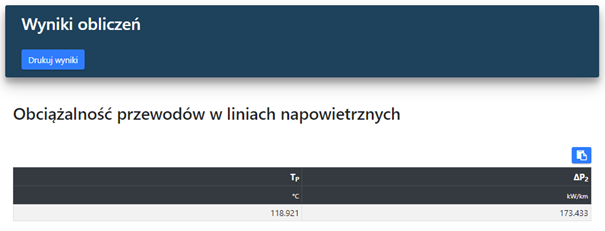
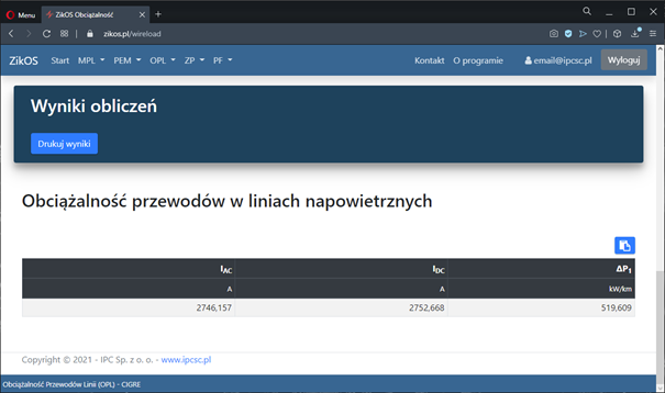
A tabular summary of the following values is presented as the results of the calculations:
- allowable current for a given temperature,
- temperature for the given current.
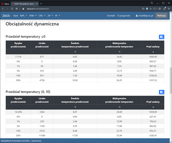
Dynamic
The input data to the calculation module are the following parameters:
- Line identification – line name, section name
- Cable data:
- kind,
- type,
- calculated diameter of the cable,
- wire diameter
- wire resistance at 20°C,
- temperature coefficient of resistance increase,
- number of aluminum layers,
- emission factors,
- absorption coefficient,
- cable roughness factor,
- Calculation conditions:
- design temperature,
- height of the line above sea level,
- difference between tension and ambient temperatures,
- minimum load current,
- maximum value of the set current,
- coefficient of variation,
- taking into account changes in the value of the flowing current,
- set analysis temperature ranges.
The results of the calculations are presented as a tabular summary of the following values for the given temperature ranges:
- risk of exceedance,
- number of exceedances,
- average temperature exceedances,
- maximum temperature exceedance,
- set current.
Short-circuit
The input data to the calculation module are the following parameters:
- Line identification:
- line name,
- section name,
- nominal network voltage,
- calculated short-circuit time,
- type of input data (short-circuit currents only or with reactances),
- soil resistivity,
- Fault currents and shares:
- three-phase current in station A,
- percentage share of the line in station A,
- three-phase current in station B,
- percentage share of the line in station B,
- single-phase current in station A,
- line percentage (in 3I0),
- single-phase current in station B,
- line percentage (in 3I0),
- Column and span data:
- pole name,
- ground resistance,
- type of lightning conductor,
- number of lightning conductors,
- span length,
- wire cross-section,
- cable diameter,
- unit resistance,
- magnetic permeability,
- distance Dmax1,
- distance Dmax2,
- distance D1-2.
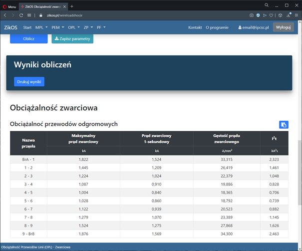
The following tables are presented as the results of the calculations:
- Load capacity of lightning conductors:
- span name,
- maximum short-circuit current,
- 1-second short-circuit current,
- fault current density,
- thermal integral I2t,
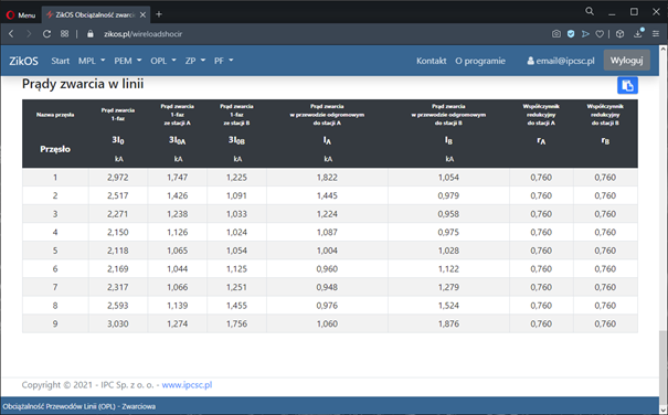
- Short-circuit current in the line:
- span name,
- single-phase short-circuit current (3I0),
- single-phase short-circuit current from station A,
- single-phase short-circuit current from station B,
- fault current in the lightning conductor to station A,
- fault current in the lightning conductor to station B,
- reduction factor to station A,
- reduction factor to station B.