
The ZikOS program is used for a comprehensive analysis of the operating states of overhead power lines. The ZikOS system enables analysis of cable mechanics, line electrical parameters and line impacts on the environment. The developed solutions enable advanced analysis of the current line condition, effective design of new and modernized lines, and effective assessment of environmental threats related to their operation.
Electric shock hazard
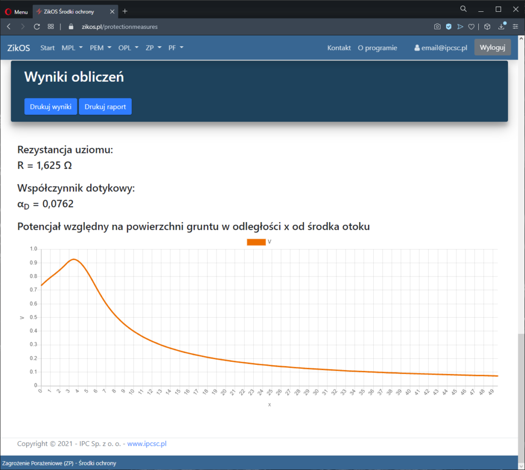
Determination of grounding voltages and contact shock voltages at supporting structures and the potential distribution on the ground surface near these structures.
Analysis of disturbance states in the line – an earth fault is simulated on each line support structure and the short-circuit currents, earth currents, earth voltages and shock voltages at the support structure are determined. For a given short-circuit duration, the determined contact shock voltage is compared with the permissible value.

The POR module allows you to determine:
- earthing voltages of poles
- voltage distribution around the pole after applying selected protection measures (earth electrodes).
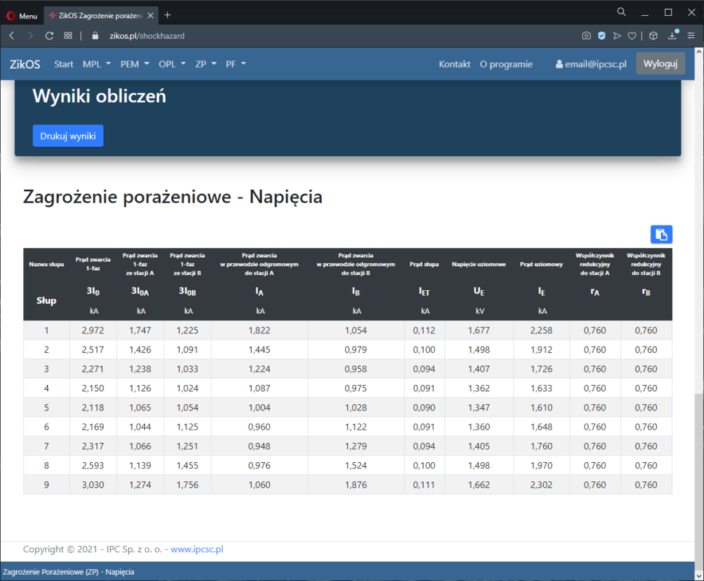
Voltages
The input data to the calculation module are the following parameters:
- Line identification
- line name,
- section name,
- nominal network voltage,
- calculated short-circuit time,
- type of input data (short-circuit currents only or with reactances),
- soil resistivity,
- Fault currents and shares:
- three-phase current in station A,
- percentage share of the line in station A,
- three-phase current in station B,
- percentage share of the line in station B,
- single-phase current in station A,
- line percentage (in 3I0),
- single-phase current in station B,
- line percentage (in 3I0),
- Column and span data:
- pole name,
- ground resistance,
- additional resistance,
- touch factor,
- type of lightning conductor,
- number of lightning conductors,
- span length,
- wire cross-section,
- cable diameter,
- unit resistance,
- magnetic permeability,
- distance Dmax1,
- distance Dmax2,
- distance D1-2.
Tabular summaries of the following values are presented as the results of the calculations:
- Voltages:
- single-phase short-circuit current,
- single-phase short-circuit current from station A,
- single-phase short-circuit current from station B,
- short-circuit current in the lightning conductor to station A,
- short-circuit current in the lightning conductor to station B,
- pole current,
- ground voltage,
- ground current,
- reduction factor to station A,
- reduction factor to station B,
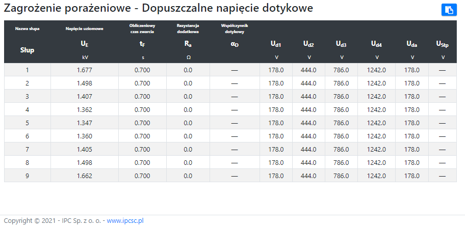
- Permissible touch voltages:
- ground voltage,
- calculated short-circuit time,
- additional resistance,
- touch factor,
- Ud1,
- Ud2,
- Ud3,
- Ud4,
- Uda,
- Ustp.
Protection measures
The input data to the calculation module are the following parameters:
- Parameters of ring earth electrodes:
- band width,
- tape thickness,
- depth of burying the earth electrode,
- soil resistivity,
- type of earth electrode (o – ring ring, □ – contour ring),
- radius or length of side a1,
- length of side a2,
- Parameters of vertical earth electrodes:
- bar diameter,
- depth of immersion of the upper end of the earth electrode,
- length of the vertical earth electrode,
- soil resistivity,
- location of earth electrodes in the XY system,
- Parameters of earth electrode branches:
- band width,
- tape thickness,
- depth of burying the earth electrode,
- tape length,
- soil resistivity,
- Parameters of the foundation earth electrode:
- axial spacing of foundation members,
- length of the side of the contour earth electrode,
- depth of burying the foundation footings,
- earthing resistance of the foundation system (from column data),
- Selection of earth electrode elements for calculations:
- ring earth electrodes,
- vertical earthings,
- branches,
- foundation earthing.
The following values are presented as the results of the calculations:
- resultant resistance of the earth electrode,
- touch factor,
- potential distribution on the surface at a specific distance from the center of the envelope.